Earlier we had discussed regarding the diode charactersitics.Diodes when connected in a particular manner can produce different waveforms across the output.We will discuss such diode configurations in this post.
1.AND gate using diodes

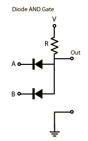
Above circuit shows an
AND gate configured using diodes connected in parallel.When the input V is applid such that the anode is at a higher potential than the cathode the diode is forward biased giving an output .Thus the circuit gives a positive output .Even if one of the diodes is reverse biased the output is zero,since the output terminal is grounded.
2 .OR gate using diodes

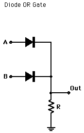
Above circuit shows an OR gate configured using diodes.
Even if a single input is such that the diode in series with the source is forward biased then the output is in high state .Only when both the inputs are such that the diodes are reverse biased then the output will be zero.
3.Half wave rectifier using diodes

The above circuit shows the configuration of half-wave rectifier using diodes.During the positive half cycle of the input waveform the diode is forward biased and it replicates the input waveform as it is .During the negative half cycle the diode is reverse biased and acts like an open circuit.Thus the output is zero for the negative half cycle of the input waveform.
4.Full wave rectifier using diodes:

If two diodes are connected such that their two cathodes and two anodes are connected back to back then the circuit acts as a full wave rectifier.During the positive half cycle diode d1 conducts while in the negative half cycle diode d2 conducts.The net voltage is the phasor sum of the two voltages and we get a steady curve across the output.
5.Bridge rectifier circuit:
In bridge rectifier circuit four diodes are connected such as shown above.
During the positive half cycle of the ac input the diodes D1 ad D2 are forward biased,while in the negative half cycle diodes D3 and D4 are forward biased.Thus throughout the input cycle the output is maintained steady giving a fully rectified signal.
No comments:
Post a Comment