We Have discussed two varieties of bias connections.we will consider few more bias connections in this post.
a.emitter bias:

In emitter bias configuration the input is applied across the base and the emitter and the output
is taken across the collector and emitter.
Ib=(vee-0.7)/rb+(h+1) re
Ic=h* Ib
Ie=(h+1) Ib
Vce=vcc-Ic*(rc+re)
B.collector feedback bias:
This configuration employs negative feedback to prevent thermal runaway and stabilize the operating point. In this form of biasing, the base resistor is connected to the collector instead of connecting it to the DC source . So any thermal runaway will induce a voltage drop across the resistor that will throttle the transistor's base current.

Vcc=(Ic+Ib) Rc+Ib*Rb+vbe
Ib=(Vcc-vbe)/Rb+(h+1) Rc
Ic=h*Ib
Vce=Vcc-Ic*Rc
C.emitter feed back bias:
The fixed bias circuit is modified by attaching an external resistor to the emitter. This resistor introduces negative feedback that stabilizes the Q-point.
The way feedback controls the bias point is as follows. If Vbe is held constant and temperature increases, emitter current increases. However, a larger Ie increases the emitter voltage Ve = IeRe, which in turn reduces the voltage VRb across the base resistor. A lower base-resistor voltage drop reduces the base current, which results in less collector current because Ic = β IB. Collector current and emitter current are related by Ic = α Ie with α ≈ 1, so the increase in emitter current with temperature is opposed, and the operating point is kept stable.
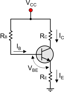
Ib=(Vcc-vbe)/(rb+(h+1) re)
Ic=h*Ib
Ie=(h+1)*Ib
Vce=Vcc-(Ic*Rc)-(Ic*Re)
a.emitter bias:
In emitter bias configuration the input is applied across the base and the emitter and the output
is taken across the collector and emitter.
Ib=(vee-0.7)/rb+(h+1) re
Ic=h* Ib
Ie=(h+1) Ib
Vce=vcc-Ic*(rc+re)
B.collector feedback bias:
This configuration employs negative feedback to prevent thermal runaway and stabilize the operating point. In this form of biasing, the base resistor is connected to the collector instead of connecting it to the DC source . So any thermal runaway will induce a voltage drop across the resistor that will throttle the transistor's base current.


Vcc=(Ic+Ib) Rc+Ib*Rb+vbe
Ib=(Vcc-vbe)/Rb+(h+1) Rc
Ic=h*Ib
Vce=Vcc-Ic*Rc
C.emitter feed back bias:
The fixed bias circuit is modified by attaching an external resistor to the emitter. This resistor introduces negative feedback that stabilizes the Q-point.
The way feedback controls the bias point is as follows. If Vbe is held constant and temperature increases, emitter current increases. However, a larger Ie increases the emitter voltage Ve = IeRe, which in turn reduces the voltage VRb across the base resistor. A lower base-resistor voltage drop reduces the base current, which results in less collector current because Ic = β IB. Collector current and emitter current are related by Ic = α Ie with α ≈ 1, so the increase in emitter current with temperature is opposed, and the operating point is kept stable.
Ib=(Vcc-vbe)/(rb+(h+1) re)
Ic=h*Ib
Ie=(h+1)*Ib
Vce=Vcc-(Ic*Rc)-(Ic*Re)
No comments:
Post a Comment