The transistors and their configurations have been discussed in our previous post.
So let us discuss the two frequently used biasing techniques in this post.
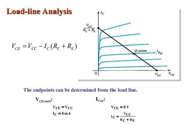
Before we get into the details of the above mentioned techniques,it is important to get an understanding of Q point or quiscient point.If we plot the Vc vs Ic curve we get the load characteristics of the BJT.On the other hand the plot of Ic for different values of Ib is taken.The intersection of these plots gives the Q point.
This analysis is called as load line analysis.
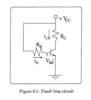
Fixed bias:
When the transistor is connected in fixed bias,the base is common to both input and output and a fixed dc supply is given to the collector and base.
Fixed Bias or Base Bias. In this condition a single power source is applied to the collector and base of the transistor using only two resistors. Applying KVL to the circuit, Thus, by merely changing the value of the resistor the base current can be adjusted to the desired value
The various equations which can be derived for this bias are as below:
Ib=(Vcc-Vbe)/Rb
Ie=Ve/Re
Ic =h Ib
where h is the ac gain.
Voltage divider circuit:

Equations governing this bias are:
Vb=Vcc*R2/((R1)+R2))
Ve=Vb-0.7
Ie=Ve/Re
Ic can be approxiately taken to be equal to Ie.
Ib=Ie/(h+1)
where h is ac gain
Vce=Vcc-Ic(Rc+Re)
So let us discuss the two frequently used biasing techniques in this post.
Before we get into the details of the above mentioned techniques,it is important to get an understanding of Q point or quiscient point.If we plot the Vc vs Ic curve we get the load characteristics of the BJT.On the other hand the plot of Ic for different values of Ib is taken.The intersection of these plots gives the Q point.
This analysis is called as load line analysis.
Fixed bias:
When the transistor is connected in fixed bias,the base is common to both input and output and a fixed dc supply is given to the collector and base.
Fixed Bias or Base Bias. In this condition a single power source is applied to the collector and base of the transistor using only two resistors. Applying KVL to the circuit, Thus, by merely changing the value of the resistor the base current can be adjusted to the desired value
The various equations which can be derived for this bias are as below:
Ib=(Vcc-Vbe)/Rb
Ie=Ve/Re
Ic =h Ib
where h is the ac gain.
Voltage divider circuit:
Equations governing this bias are:
Vb=Vcc*R2/((R1)+R2))
Ve=Vb-0.7
Ie=Ve/Re
Ic can be approxiately taken to be equal to Ie.
Ib=Ie/(h+1)
where h is ac gain
Vce=Vcc-Ic(Rc+Re)
No comments:
Post a Comment