The transistor symbol and characteristics have been discussed in a previous post.The transistor behaviour is different under low frequency and high frequency conditions.The transistor has two capacitances Cbe and Cbc between the base emitter and the base collector terminals.
1.Under low frequency conditions the reactance is high because of the low values of capacitance and frequency both.So it can be considered as open circuit.
2.On the other hand under high frequency conditions the capacitance and frequency values cause a considerable reactance,leading to a voltage divider configuration.Hence the gain of the circuit is impacted.
For low frequency analysis the two port equivalent circuit is used.
The h parameters are used to relate the voltage and current in output and input of a transistor.
v1=h11*i1+h12*v2
i2=h21*i1+h22*v2
h11=(v1/i1)at v2=0{input resistance at output short circuit}
h12=(v1/v2)at i1=0{reverse transfer ratio}
h21=(i2/i1) at v2=0{forward transfer ratio}
h22=(i2/v2)at i1=0 {output conductance at input open circuit }
The transistor equivalent circuit at low frequency is as below:

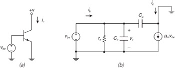
The transistor model at high frquencies is shown below:
1.Under low frequency conditions the reactance is high because of the low values of capacitance and frequency both.So it can be considered as open circuit.
2.On the other hand under high frequency conditions the capacitance and frequency values cause a considerable reactance,leading to a voltage divider configuration.Hence the gain of the circuit is impacted.
For low frequency analysis the two port equivalent circuit is used.
The h parameters are used to relate the voltage and current in output and input of a transistor.
v1=h11*i1+h12*v2
i2=h21*i1+h22*v2
h11=(v1/i1)at v2=0{input resistance at output short circuit}
h12=(v1/v2)at i1=0{reverse transfer ratio}
h21=(i2/i1) at v2=0{forward transfer ratio}
h22=(i2/v2)at i1=0 {output conductance at input open circuit }
The transistor equivalent circuit at low frequency is as below:
The transistor model at high frquencies is shown below:
The Miller effect occurs only in inverting amplifiers –it
is the inverting gain that
magnifies the feedback capacitance.
Hi
No comments:
Post a Comment