Logic gates are the basic building blocks of any electronic network.They have two or more inputs and only one output.The relationship between the output and input is based on a certain logic.
Mentioned below are the symbols of the logic gates.
The AND,OR and NOT gates are the gates we commonly come across in our circuits.
Apart from these NAND and NOR gates can also be to configure an electronic circuit.Only NAND gates or only NOR gates can be used to prepare a logic circuit.Hence the NAND or NOR gates are called as universal gates.
1.AND gate

The AND gate gives a high output only when all its inputs are high.
2.OR gate
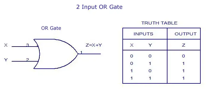 The or gate gives a low output when all its inputs are low.
3.NOT gate:
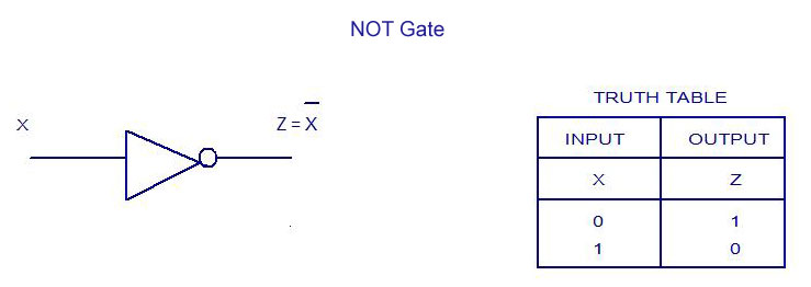
The not gate perform the complement of the input signal.
4. NAND gate:
The complement of the AND gate is achieved by a NAND gate.
The NAND gate gives a low output only when all its inputs are high.

Since the output assumes the high state even if one of its inputs is low NAND gate is also called as active low OR gate.
5.NOR gate
The complement of the OR gate gives the NOR gate.
The expression for a NOR gate is the result of adding a NOT gate to the OR gate.

Since its output assumes the high state only when all its inputs are zero, a nor gate is also called active low AND gate.
6.EX-OR gate:
The output is in logic one if any one of the inputs is 1.Since the output is 1 when the inputs are unequal the exclusive or gate is called inequality detector.

The output expression for inputs A and B can be represented as Y =A'B+AB'
7.EX-NOR gate:
An X-NOR gate is the complement of EX-OR gate.The output of X-NOR gate is low when even if only one of the inputs is high.The output takes a logic 1 when both of the inputs are 1 or 0.
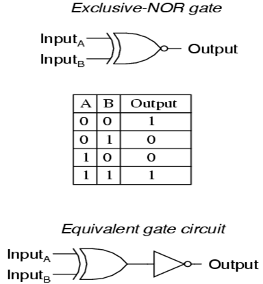
Since the output is 1 only when both inputs are same the EX-NOR gate is also called as equality detector.
Mentioned below are the symbols of the logic gates.
The AND,OR and NOT gates are the gates we commonly come across in our circuits.
Apart from these NAND and NOR gates can also be to configure an electronic circuit.Only NAND gates or only NOR gates can be used to prepare a logic circuit.Hence the NAND or NOR gates are called as universal gates.
1.AND gate
The AND gate gives a high output only when all its inputs are high.
2.OR gate
The or gate gives a low output when all its inputs are low.3.NOT gate:
The not gate perform the complement of the input signal.
4. NAND gate:
The complement of the AND gate is achieved by a NAND gate.
The NAND gate gives a low output only when all its inputs are high.
Since the output assumes the high state even if one of its inputs is low NAND gate is also called as active low OR gate.
5.NOR gate
The complement of the OR gate gives the NOR gate.
The expression for a NOR gate is the result of adding a NOT gate to the OR gate.
Since its output assumes the high state only when all its inputs are zero, a nor gate is also called active low AND gate.
6.EX-OR gate:
The output is in logic one if any one of the inputs is 1.Since the output is 1 when the inputs are unequal the exclusive or gate is called inequality detector.
The output expression for inputs A and B can be represented as Y =A'B+AB'
7.EX-NOR gate:
An X-NOR gate is the complement of EX-OR gate.The output of X-NOR gate is low when even if only one of the inputs is high.The output takes a logic 1 when both of the inputs are 1 or 0.
Since the output is 1 only when both inputs are same the EX-NOR gate is also called as equality detector.
No comments:
Post a Comment